
I first want to acknowledge that I did the thing that I try to never do: I showed off a snazzy project, left some hints here and there of how it worked, said I would follow up with full details… and never did. That’s lame.
I’ve had multiple people reach out for more info and I’m glad they did, since that’s pushed me to finally get some repos public and this belated follow-up written. Apologies!
To jump straight to it, I’ve published these two repos:
Update March 2025: The main repo URL has been updated as this is now a library.
Hardware
Let’s first go over the hardware involved. The most important piece, of course, is the Alfa-Zeta XY5.
In my case, the 14×28 board was made up of two 7×28 panels connected together via RJ-11.
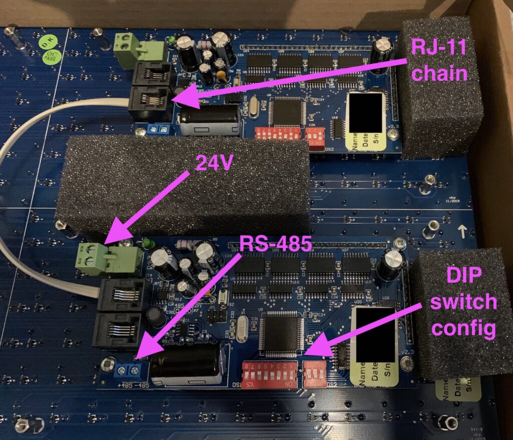
The panels are pricey, but they can be thought of as “hardware easy-mode”. Alfa-Zeta has done the hard job building the controller that drives the hardware and all we have to do is supply power and an RS-485 signal that abides by their protocol.
If you purchase a panel from them there are two important documents to request:
- The main manual that describes the specs, features, and things like the DIP switch settings.
- The protocol for sending commands to the controllers (which is really simple).
These can easily found by searching around, but if you own a panel the company should supply them. Most of the protocol can be deduced by looking at open source code.
Components
- Alfa-Zeta XY5 – 14×28 Flip Dot display
- NodeMCU ESP8266 – MCU
- 3.3v RS-485 to TTL – Allows the MCU to communicate over RS-485
- ALITOVE AC 100-240V to DC 24V 5A Power Supply – Required to power the panels
- BINZET DC 12V 24V to 5V 5A – Optional, used to step down power to the MCU so we have one power source
The 24V -> 5V converter isn’t necessary if you supply power to the MCU independently, say through a USB power adapter.
Connection overview
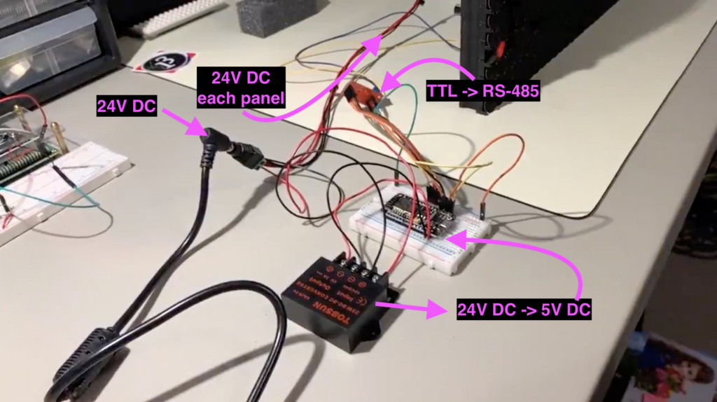
- 24V DC goes to both panels
- 24V DC goes to the step-down converter, 5V DC goes to the 5V input of the NodeMCU
- NodeMCU is wired to the RS-485 to TTL converter
VCC -> 3.3vGnd -> GndDE -> 3.3v pulled high because we're always transmittingRE -> 3.3v pulled high because we're always transmittingDI -> TX[x] x being 0 or higher depending on boardRO -> RX[x] most boards only have the main serial IO, but boards like the Mega have multiple
- RS-485 -> Only one panel controller – not both
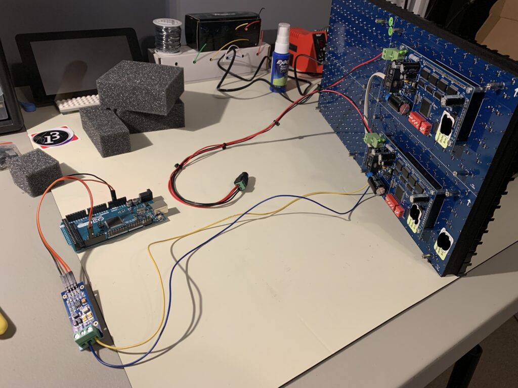
An Arduino Mega is driving the board in this photo.
Software
The MCU
See https://github.com/twstokes/flipdots for the code that runs on the MCU.
At the moment there isn’t much to it – you can either compile the firmware to run in a mode that writes data from UDP packets to the board, or you can draw “locally” using Adafruit GFX methods.
See the README in the repo above for more details.
iOS / iPadOS / macOS
See https://github.com/twstokes/flipdots-ios for the code that runs on these devices.
Semi-interestingly I utilized Adafruit GFX again, this time via swift-gfx-wrapper to draw to the board over UDP. It’s hacky and experimental, but that’s part of the fun.
See the README in the repo above for more details.