I’ve had an Adafruit NeoTrellis M4 Express for a while and it’s a lot of fun to play with. It’s got NeoPixel illuminated buttons, audio capabilities, a powerful SAMD51 CPU, and a lot of potential.
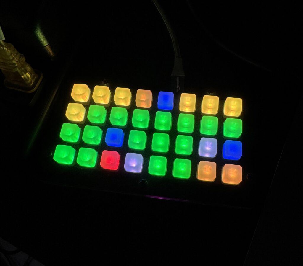
I’m on the Apps Infrastructure team at Automattic, so I thought it would be cool if I could make it represent the states of our Buildkite builds on the board. Green would mean the build passed, red would mean failed, pulsating yellow if running, etc. Pressing the button would open the build directly in my browser.
So that’s exactly what was built! Thanks to AI tooling I was also able to add some goodies like simulators for the Trellis as well as incoming Buildkite data.
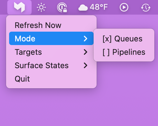
Builds can be filtered in a menu bar app by queue or pipeline, as well as states (e.g. just show me failing builds).
Years ago I slapped together a way to run DOOM on Apple devices by wrapping doomgeneric with SpriteKit. The task was relatively straightforward, and I shared some technical details in the original post. What was most exciting to me about the weekend project was witnessing a game that took every bit of my ’90s home computer now running effortlessly on my wrist. It would’ve been even cooler if it had sound on the Watch, but I learned that wasn’t going to come easily and needed more of my time and attention than I had to spare. A common theme with having so many side projects.
Then AI coding tools arrived and they’re the side project game changer. For this particular case I wasn’t in it for the academic exercise – I just wanted to point and get what I wanted, so I did just that.
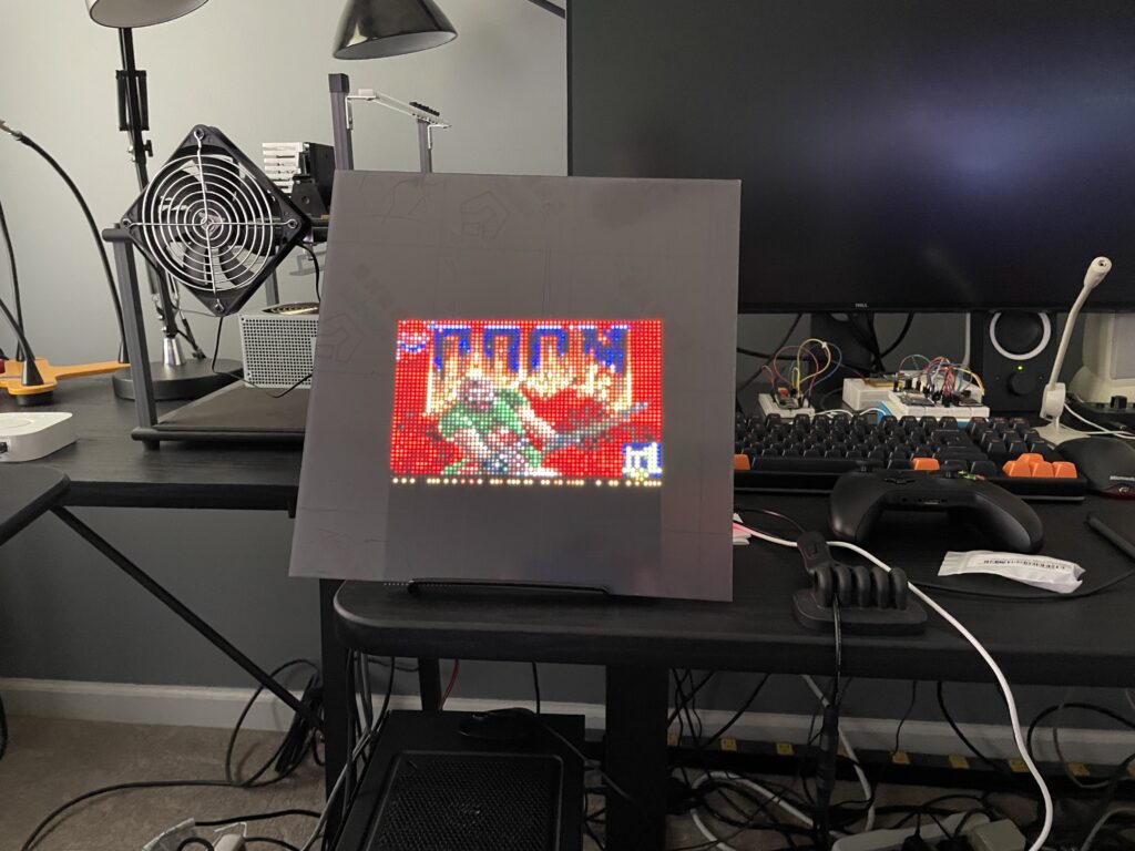
Presenting DarwinDOOM, formerly known as AppleGenericDoom!
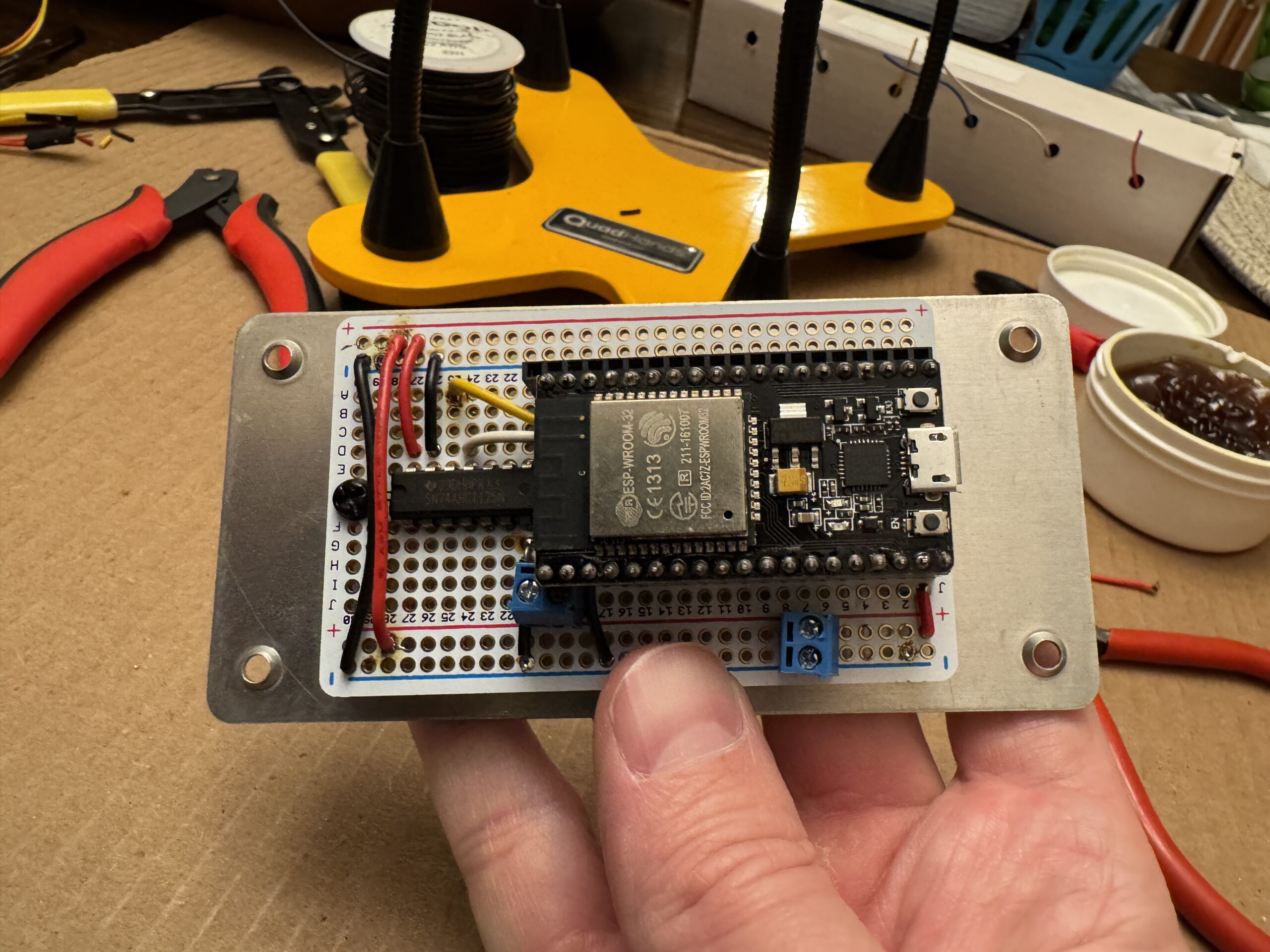
The ESP8266 was swapped for an ESP-WROOM-32 with dual cores
At the end of 2024 I experienced stability issues when updating many LEDs rapidly, e.g. a looping rainbow effect with a really low delay set. After some indeterminate amount of time the tree would crash and restart itself. I initially assumed it was bad C code on my part, but failed to spot anything and eventually put the tree away sometime in January of 2025 because it just got awkward. Now that we’re back to a socially acceptable time to have a Christmas tree out I’ve had a chance to do some deeper digging.
I added a new command to have the ESP return the reason it reset which was really helpful in confirming my suspicion that the ESP8266 just didn’t have enough oomph to drive pixels and run WiFi concurrently:
Long-ish story short I upgraded to an ESP32 with two cores (note: number of cores is model-dependent) and this provides the necessary headroom to bit bang LEDs and run WiFi stably. It required some re-soldering of the Perma-Proto board (since the pin layouts are different) as well as some code changes, but overall it was a relatively quick and straightforward upgrade. The tree hasn’t crashed since!
I mentioned in my previous post about the Juicy Crumb DockLite G4 that there were two shortcomings with the product:
Their software to control the brightness of the display was macOS only.
The display doesn’t support sleep, so you’re required to press a physical button to turn off the backlight.
Thanks to some USB packet snooping and GPT, both of these problems were solved quickly. 😎
I wanted Linux software control
What started this exploration was that I wanted to control the display from Linux because it’s currently connected to a Raspberry Pi, not a Mac.
Step 0: Check for an open source repo
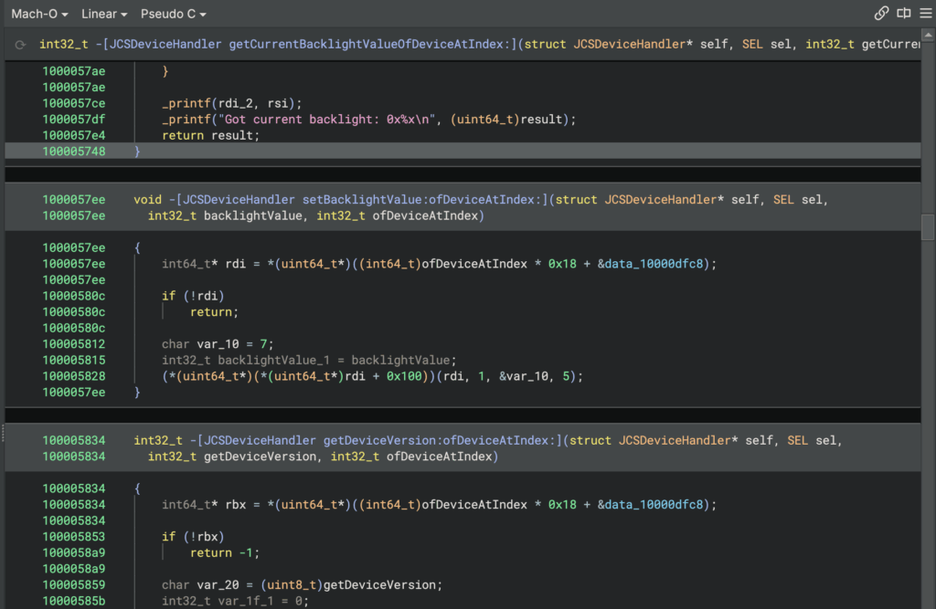
Negative. I didn’t spot anything, so it’ll take a little more grunt work. I did run their helper app through a disassembler and spotted functions like getting and setting the backlight via IOKit which were all expected. It wasn’t necessary to go this far, it just confirms that we have some USB packet snooping to do.
Step 1: Get lsusb output
Running lsusb with the display connected to the RPi showed:
Bus 001 Device 009: ID 4a43:1d8a Juicy Crumb Systems DockLite
So I grabbed the output of lsusb -v -d 4a43:1d8a to feed it to the LLM later to provide more details about its USB specs.
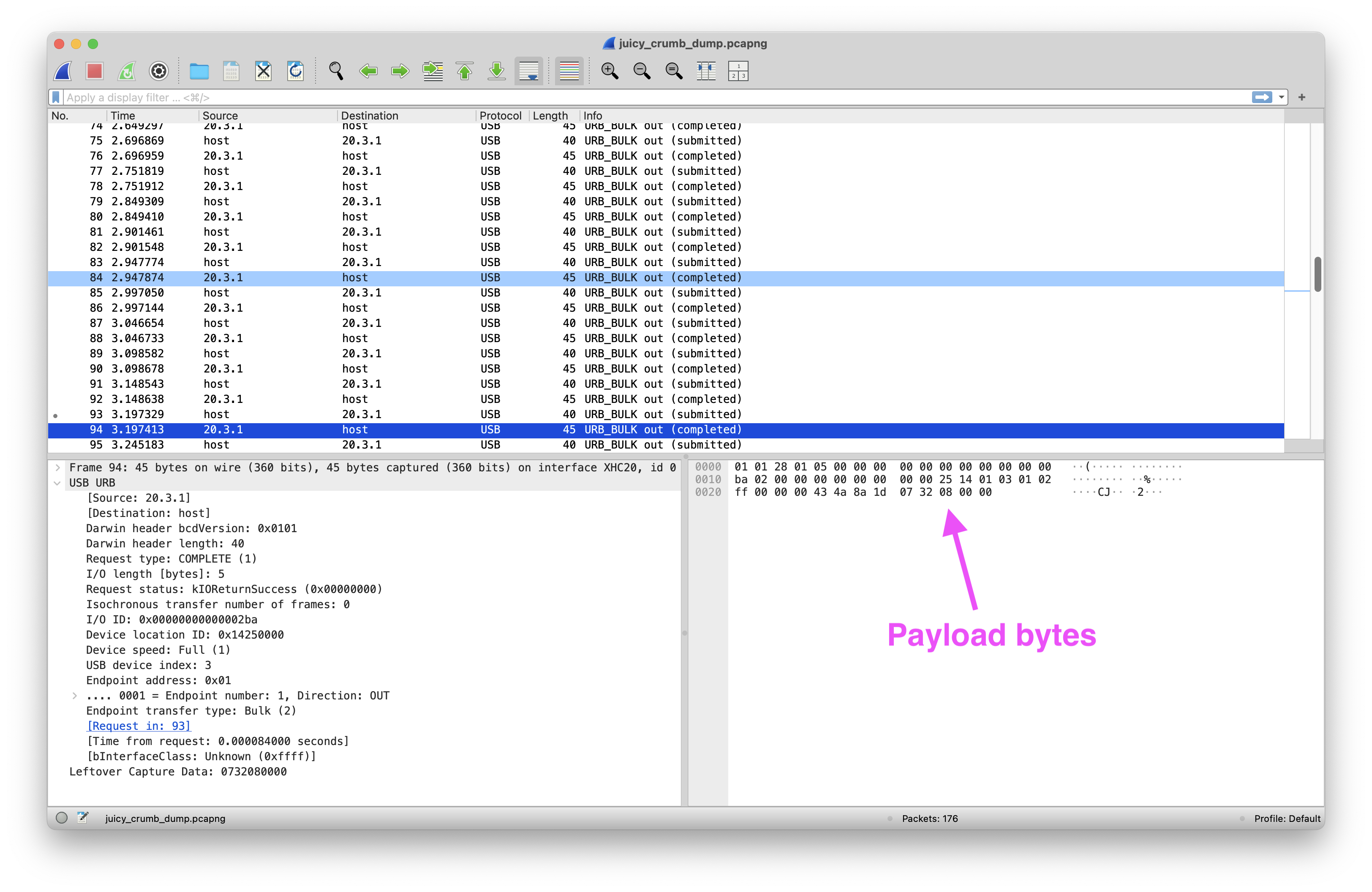
Step 2: Capture USB packets on the Mac
The double-edged sword of Apple’s security is that it introduces all sorts of challenges for devs who need to get to lower level functionality, like capturing raw data from interfaces.
To successfully USB capture packets on a Mac I had to:
After installing the pyusb module I could run python set-brightness.py 700 and it worked from Linux! The range from lowest backlight brightness to highest is around 700 – 5000.
The extra bonus (which I’m most excited about) is that sending a value of 0 will truly turn off the backlight! This isn’t even (currently) possible with their software. (Obligatory “do this at your own risk”)
Now I can hook into something like D-Bus signals to potentially toggle the display depending on the desktop’s locked state.
Success
✅ The display’s brightness can be set from any OS, not just macOS.
✅ The display’s backlight can be turned off via software.
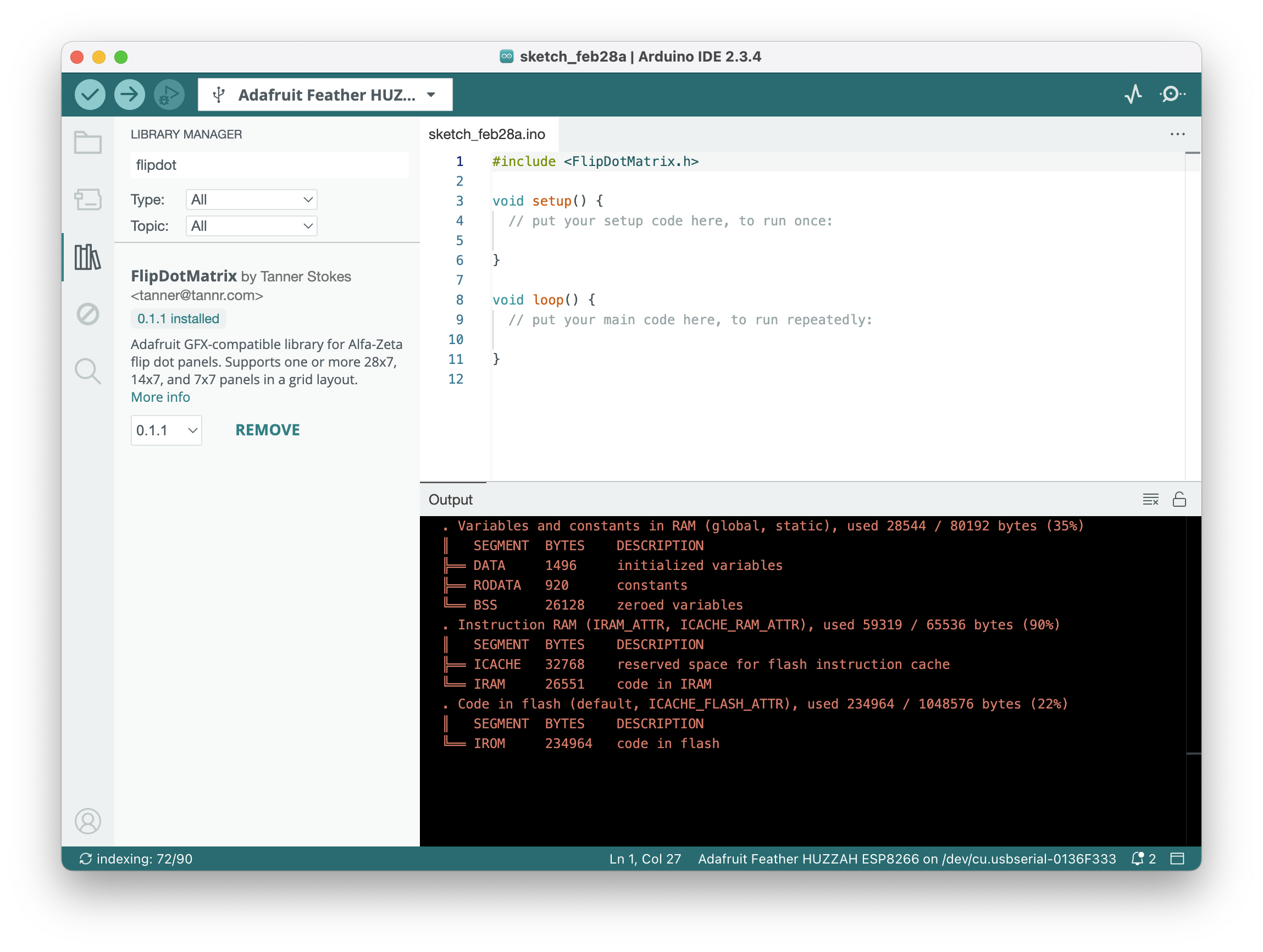
In the past I’ve blogged about my Alfa-Zeta flip dots (one, two) and how I got them working with the Arduino platform. I’ve taken some time to turn the work into a consumable library that should make it much easier for others who want a turn-key way to drive the display.
The library is available in the Arduino IDE as well as the PlatformIO registry and comes with examples to get started. When added to a project it’ll grab all its dependencies so you can get going as quickly as possible.
Most of the heavy lifting is done by the excellent Adafruit GFX Library and it’s been updated to support 7×7 and 14×7 panels in addition to 28×7. Flip on! 🔴
Back around the time the first iPhone was released (feeling old! 😬) I was taking a course where we built a CPU-based ray tracer in C.
If you’re not familiar with the ray tracing technique, check it out here.
What I mostly remember from the course was math, pointers, and segfaults. Oh the segfaults. By the end of the course, however, I had a decent grasp on C and that’s been a valuable skill so many times in my career and hobbies.
How the original project functioned
You wrote an input file that describes various shapes, light sources, and attributes of the environment.
You fed the file into the C program.
You waited a bit (remember, we’re doing everything on the CPU in ~2007).
You got a fancy PPM file. (PPM was a great image format due to its simplicity – we were dealing with enough!)
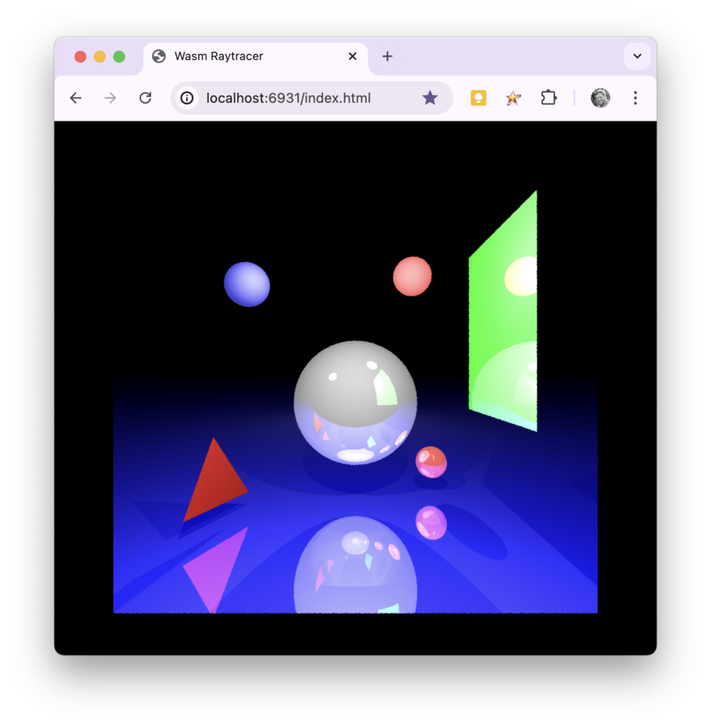
Wasm motivation
Recently I decided that I wanted to learn more about the inner workings of WebAssembly (Wasm) and figured this would be a great candidate project. It’s fully contained without any external dependencies, *I wrote all the code so it shouldn’t be too mysterious, and if I got it to work there would be a visual payoff.
*Feel free to judge some of the rough spots in the code – it was a long time ago!
Process
The first thing I made sure of was that I could compile the project locally the non-Wasm way. There were no hiccups there – it worked on the first try using the Makefile. ✅
I then started reading this tutorial on converting a C project to Wasm. After installing emscripten on macOS (I used Homebrew) I decided to add a new C source file to the project and added a function that looked something like:
#include "emscripten.h"

EMSCRIPTEN_KEEPALIVE
int version() {
  return 42;
}
If I could get this to work I could at least get information from C -> JS for starters. All that it took to make this work was:
Substituting gcc with emcc in the Makefile
Making sure I added the EXPORTED_RUNTIME_METHODS='["cwrap"]' compiler flag
Calling Module.cwrap from JS to use the function
That was pretty much it. I’m not going to go super in-depth with this blog post because I think most of it can be figured out from the source.
Next challenges
I had a bit more to go but was surprised at how easy it was to send a value from C to JS. The next items to figure out were:
The ray tracer expected an input file and an output file, how would this work with a browser?
We can pass integers easily, but what about the big array of pixel data when we ultimately generate an image?
Where would our C calls to fprintf and its siblings go when trying to debug to stdout and stderr?
What about main – does it run?
I’ll go ahead and spoil these really quickly in their respective order:
fmemopen saved the day by taking the input string (which is a char *) and providing a FILE type in return which is an in-memory buffer stream. In other words, no massive overhauling needed although we aren’t using “real” files anymore. In addition a slight refactoring was done to the project to return an array of pixels rather than write out an image file.
They automagically show up in the browser console! This is a really nice feature, and stderr calls are even properly displayed as errors.
Yes! In my case I got rid of it because it was prompting for the CLI input, but it was interesting to see that it automatically ran. There may be a compiler setting to disable this.
A summary of what it took to convert the ray tracer to Wasm
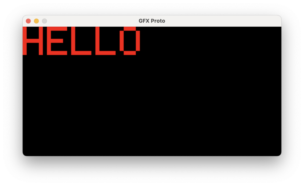
I’m starting to dust off some seasonal projects and realized I hadn’t made this simple tool public which others may find handy. With projects like the NeoPixel Tree it can be much quicker to code visual sequences locally instead of waiting for new firmware to upload to the MCU every time you want to tweak something.