Today our home Internet went out. It rarely happens, but when it does it’s typically brief – maybe a couple hours max, and I can hobble along with my Mac connected directly to my phone until it comes back. Today’s outage was a lot longer, though, and after a few hours I really wanted to get the entire house back online so all of my Internet dependent devices could get back to normal.
My hope initially was that my MikroTik router would allow me to connect up my iPhone via USB and bridge the hotspot to the rest of my network, but I couldn’t make that work.
Update: It looks like MikroTik tethering support may come in RouterOS 7.22!
The router identified that the phone was connected, but it wasn’t treating it like a USB Ethernet interface. I could’ve devoted one of its radios to connect wirelessly to the phone, but I really didn’t want to mess with my router’s configuration knowing that this would be a temporary setup.
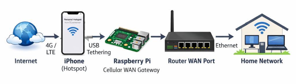
Using Linux to do this (in my case a Raspberry Pi) was super simple. Here’s what I had to do to share the iPhone’s Internet connection with my entire network. Afterwards everything worked as it should – wireless and wired devices could all reach the Internet.
On the phone
Specs: iPhone 15 Pro on AT&T
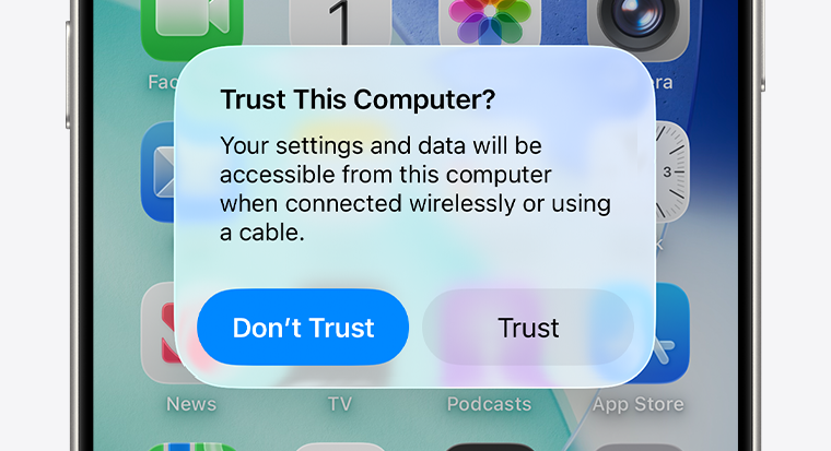
Just make sure Personal Hotspot is enabled (you need a cellular plan that allows tethering), and connect it to a USB port on the Pi. You should get a prompt on both devices to trust the other one. This is likely the same experience if you have an Android device.
On the RPi
Specs: RPi 5 running Bookworm + Gnome
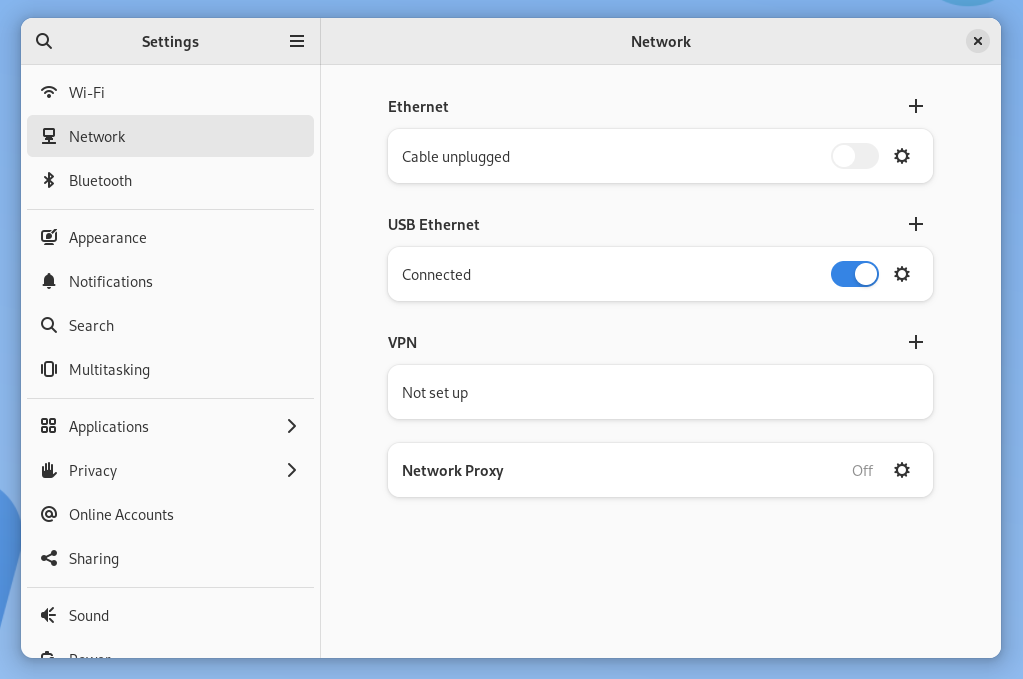
With the iPhone connected, tethering was already working! It showed up as an interface named eth1 and traffic was successfully routed. Kudos to the folks who made this so easy to get going.
The next step was to turn the RPi into a gateway that we could plug into our router’s WAN Ethernet port.
Here are some assumptions I’ll use for the commands below:
eth0is the Raspberry Pi’s Ethernet interfaceeth0will have an IP of192.168.88.1/24eth0will serve a DHCP range of192.168.88.10 - 192.168.88.100eth1is the iPhone’s USB Ethernet interface
With root permissions we need to do the following:
- Enable packet forwarding:
sysctl -w net.ipv4.ip_forward=1
- Set
eth0‘s IP to192.168.88.1with a netmask of255.255.255.0.- You can use the GUI for this, or
/etc/dhcpcd.conf, or whatever’s best for your distro.
- You can use the GUI for this, or
- Install dnsmasq:
apt install dnsmasq
- Configure the DHCP range for
eth0by editing/etc/dnsmasq.conf:interface=eth0dhcp-range=192.168.88.10,192.168.88.100,255.255.255.0,24h
- Restart dnsmasq:
systemctl restart dnsmasq
- Set some iptables rules:
iptables -t nat -A POSTROUTING -o eth1 -j MASQUERADEiptables -A FORWARD -i eth0 -o eth1 -j ACCEPTiptables -A FORWARD -i eth1 -o eth0 -m state --state RELATED,ESTABLISHED -j ACCEPT
- Confirm iptables look good:
iptables -t nat -L -n -v
Note: These iptables rules won’t survive a reboot, so you’ll want to commit them if you need that. Also keep in mind you’ll likely want to disable dnsmasq and revert eth0‘s network configuration when things get back to normal.
On the router

If your router is configured to get its WAN IP via DHCP there’s nothing to do here – you just need to make sure that the Raspberry Pi’s Ethernet cable is connected to the appropriate WAN port.
If your router isn’t configured to use DHCP, just give it an IP in the range above, a gateway of 192.168.88.1, and some standard DNS servers like 8.8.8.8 and 8.8.4.4.
That’s it
Everything wired or wireless on the network just works – it doesn’t know (or care) where the WAN connection is coming from. A great solution for those days when you need a failover! 🛜