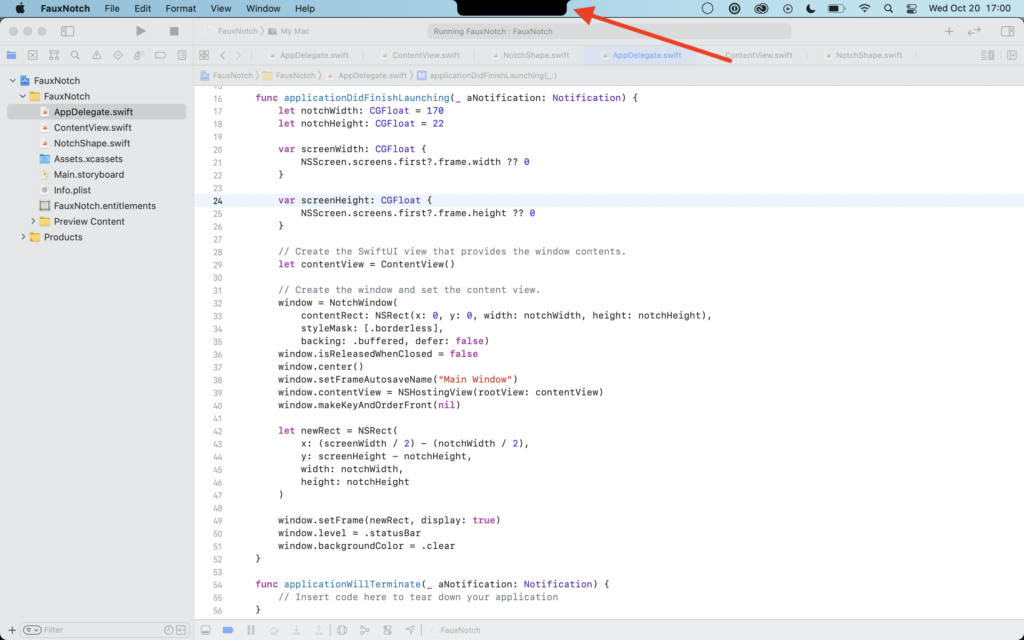
I’ve seen a lot of these little “fake notch” apps pop up since Apple’s new MacBooks were announced, but I didn’t see a lot of source code – so of course I was nerd sniped.
Here’s a basic example of making one using AppKit and SwiftUI!
 Tanner's Website
I’ve seen a lot of these little “fake notch” apps pop up since Apple’s new MacBooks were announced, but I didn’t see a lot of source code – so of course I was nerd sniped.
Here’s a basic example of making one using AppKit and SwiftUI!
I’m thrilled to be joining the fine folks at Automattic this month as a mobile software engineer. Though I’ll miss all of my wonderful Clemson coworkers immensely, I’m excited for the road ahead. 🚀
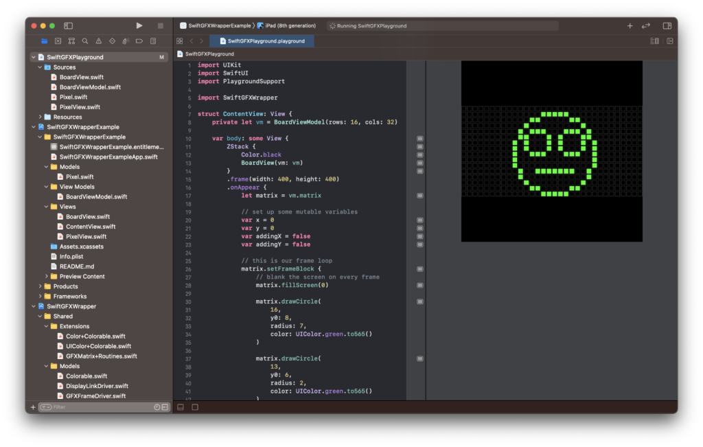
I saw flip dots (also called flip discs) last year for the first time and instantly knew I needed some in my life. If you’re not familiar with them, check out how they work!
The particular model I have is the ALFAZETA XY5, which may be the easiest way to get up and running, but certainly not the least expensive.
After getting the board, all you need is:
I plan to write in more detail how it all works, but for this demo the stack is:
Update: Here’s more info on how it all works!
Update March 2025: The main repo URL has been updated as this is now a library.
For even easier prototyping, I’ve added Swift Playground support to my SwiftGFXWrapper project!
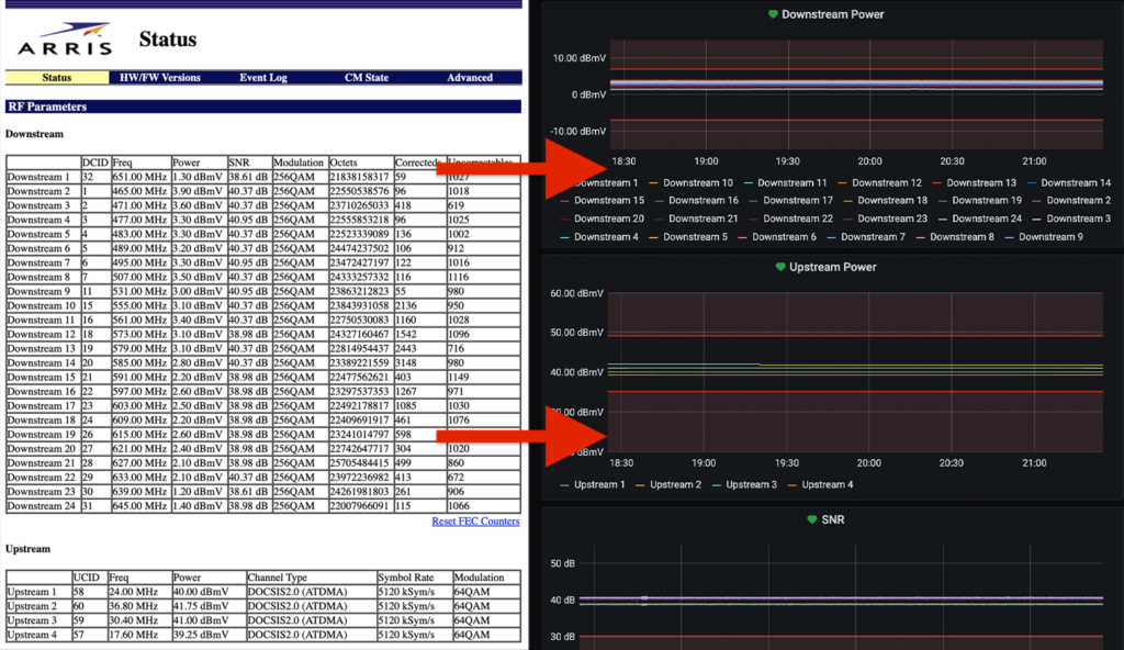
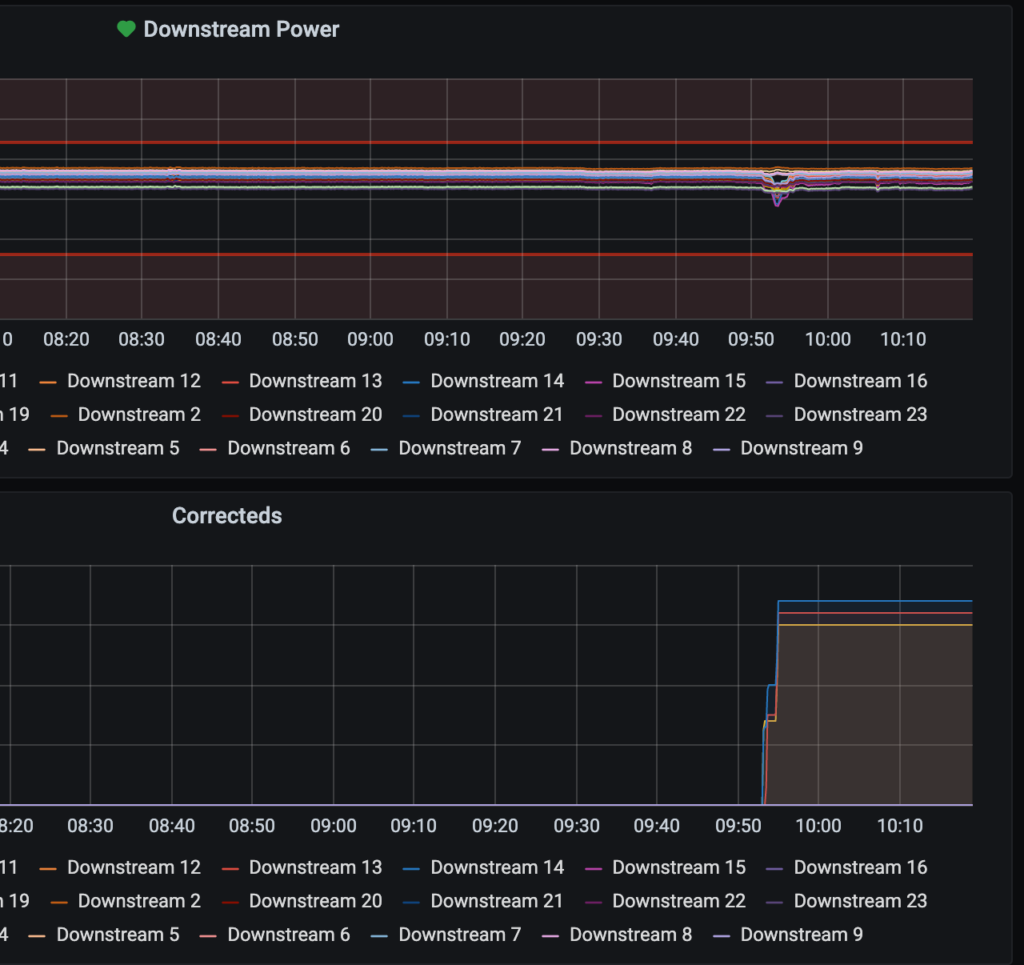
It felt good to complete this project that’s been on my list for quite some time. The main goal was to scrape the values from my modem’s status page and pipe them into InfluxDB, which feeds Grafana. Not only could I look at data trends, but I could receive alerts if certain values exceeded an acceptable threshold.
Overall this is a straightforward process:
I knew I wanted to use Python for the project, so I first looked into Scrapy. After wrapping my mind around it (somewhat) I gave it a go and actually had a working solution… but it felt way over engineered and at times inflexible for what I wanted. I threw 90% of that solution away and went with a simpler script.
What I landed on was something that’s custom and lightweight, but extendable in case someone has a different status page or wants to use an alternative to InfluxDB.
Another fun project from a few weekends ago: Wrapping the Adafruit GFX in Objective C and bridging to Swift for some neat 8-bit effects!
The most interesting component of this project so far has been building a Swift closure that is executed in C as a const void *. This was new territory for me and a lot of fun to figure out!
Currently a work in progress, I’ve nerd sniped myself to get TCP/IP working over SLIP with a pair of Arduinos equipped with nRF24L01+ radios.
SwiftUI is turning into my go-to for rapid prototyping. Here’s an example of a light / dark mode switcher that I think would work well on web…
It’s been possible to boot a Raspberry Pi from an SSD for a while now, but the process didn’t seem to have the full blessing from the Raspberry Pi Foundation. This changed recently when they announced their beta firmware to officially support it.
It was pretty painless to get it working, so here’s how I did it. Some notes up front:
Most of these instructions all came from here.
Don’t blindly follow these instructions unless this post is only a few days old! Things are bound to change – this is beta software. Do it at your own risk. If a step has something in [brackets], you need to figure out your particular value.
sudo apt updatesudo apt full-upgradesudo vim /etc/default/rpi-eeprom-updateFIRMWARE_RELEASE_STATUS="beta"sudo rpi-eeprom-update -d -f /lib/firmware/raspberrypi/bootloader/beta/pieeprom-2020-05-15.binwget https://downloads.raspberrypi.org/raspios_lite_armhf_latestshasum -a 256 raspios_lite_armhf_latest (verify the SHA)unzip raspios_lite_armhf_latestsudo dd bs=4M if=2020-05-27-raspios-buster-lite-armhf.img of=/dev/[SSD DEV NAME] conv=fsyncsudo rpi-updatesudo cp /boot/*.elf /media/[SSD mount]/bootsudo cp /boot/*.dat /media/[SSD mount]/bootsudo touch /media/[SSD mount]/boot/sshSD Reads: 42MB/sec
SD Writes: 22 MB/sec
SSD Reads: 314 MB/sec (7.4x)
SSD Writes: 212 MB/sec (9.6x)